Basically, they are a set of pins responsible for sending signals to USB ports. However, the back panel USB ports and the extension cards do not have any relation to the USB headers, as they have a direct connection to the motherboard. If you wish to learn more about USB headers on motherboard, you’re at the right place! In this article, you will learn about what USB headers are, where they are located, their different types, and how you can connect USB ports to them.
What are USB Headers and Where are They Located?
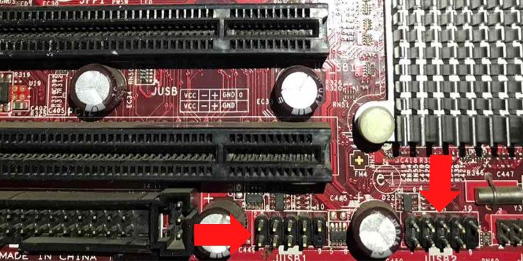
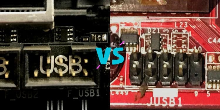
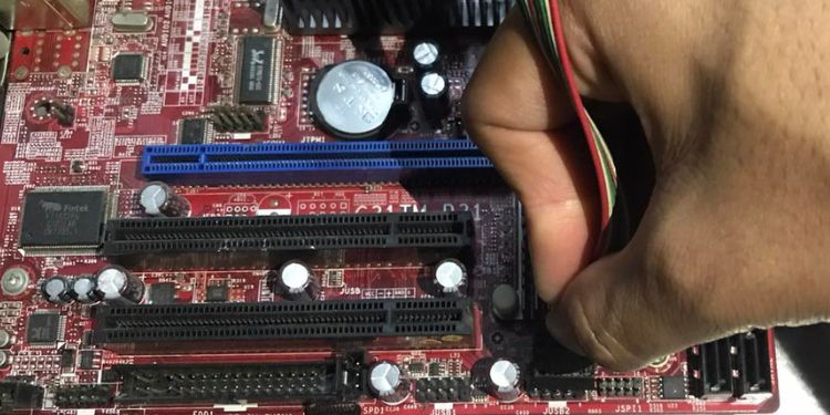
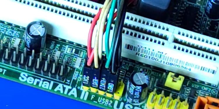
USB headers on a motherboard are simply the connectors that ensure USB devices are correctly connected. Generally, they are located on the bottom or the right side of the circuit board, depending on the type of USB header. To locate the USB headers, navigate to your motherboard and find the labels having F_USB, J_USB, FPANEL_USB, F_USB2, or similar indications. If you cannot do that, you can use your motherboard manual to detect where they exactly lie. Basically, these are just the different types of USB headers, and they differ in terms of the number of pins and their configuration. We will be discussing all of them in further sections.
Different Types of USB Headers
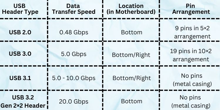
If you’re building a custom PC, it’s essential to know what USB header types your motherboard supports. Well, each of them differs based on pins and the number of USB ports they can support. Although most USB headers can use two USB ports, some only support one. Moreover, the header types correspond exactly to the USB generations. This simply means that the USB header supports only the kind of USB generation you use. For example, the USB 3.0 can’t be placed in the USB 2.0 header due to size incompatibility. To learn more, here’s a complete guide on the differences between USB 2.0 and USB 3.0. Generally, USB headers can be classified into four types or generations. In this section, we will discuss each of them in brief.
USB 2.0 Header
To confirm that you have a USB 2.0 header, you’ll see that the label on the motherboard mentions ‘USB 2.0’. Well, this is one of the most common headers and is located in the bottom part of most motherboards. Moreover, they have nine pins in a 5×2 arrangement, meaning five pins each on two rows. However, the second row has one pin missing to ensure proper alignment.
USB 3.0 or 3.2 Gen 1 Header
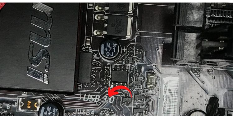
The USB 3.2 Gen 1 header, previously known as USB 3.0, is identified by the ‘USB 3.0’ label. They are located on the motherboard’s bottom or right side, depending on various types of motherboard. Although they look pretty similar to the USB 2.0 headers, they are comparatively more efficient. Moreover, they have a total of nineteen pins in a 10×2 arrangement, ten pins in the first row and nine in the second. As in the USB 2.0 headers, they also have a pin missing in the second row.
USB 3.1 or 3.2 Gen 2 Header
Like the USB 3.0 header, the USB 3.1 or 3.2 Gen 2 can be located either on the bottom or right side of the motherboard. While both the previous generations had pin arrangement, the USB 3.1 do not have such a configuration. Instead, they adopt a unique metal casing with no pins sticking out.
USB 3.2 Gen 2×2 Header
Basically, USB 3.2 Gen 2×2 header is the advanced form of the USB 3.2 Gen 2 header. However, one thing to keep in mind is that they are located only on the motherboard’s right side. Well, the only difference between these two headers lies in the channel. While the USB 3.0, 3.1, and 3.2 headers are single-channeled, the USB 3.2 Gen 2×2 supports dual channels. Interestingly, they are also called the USB Type-E header and look very identical to the USB Type-A ports. Moreover, they are rare to find and might only be available on modern and costly motherboards.
What’s the Difference Between F_USB and J_USB?
Generally, most motherboard manufacturers use F_USB1 or F_USB2 labels to indicate the front panel USB ports. So, the letter ‘F’ simply indicates ‘Front’ in the USB headers. However, you may not find the F_USB header on every motherboard. Well, the reason behind this is that some other manufacturers use a different letter to indicate the USB ports. For example, you can find J_USB1, J_USB2, or similar indications on an MSI motherboard. Moreover, most older PCs used J_USB headers, where J stood for ‘Jumper’, and they only supported half-duplex communication. Unfortunately, this created deadlock, and the USB devices often malfunctioned. Later, several manufacturers adopted USBs that supported full-duplex mode and named them F_USB. But even today, you can find J_USB on MSI motherboards that have started supporting full-duplex, and the letter ‘J’ now stands for ‘Jack’. So, the only difference between F_USB and J_USB is the indications given by different manufacturers. In fact, if you find any other letters, they also could very well mean and do the same work.
Do Back Panel USB Ports Require USB Headers?
Most users prefer the rear panel USB ports that are directly embedded into the motherboard. Thus, you do not need to connect them to the USB headers. Similarly, if you’ve added an additional USB expansion card, they are directly plugged into the PCIe slot in the circuit board. Thus, you do not require an additional USB header connection for them as well.
How Do I Connect USB Ports to the USB Headers?
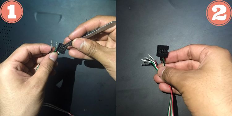
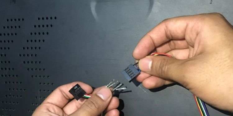
Now that you know the different types of USB headers, it’s essential to learn about the internal USB cable. Basically, they are the extension cables that let you attach the USB ports to the USB headers. In today’s market, you can find two types of internal USB cables – one with a USB header jack and another with individual wires for each pin. Although the working mechanism is the same, the connecting procedure for the latter one is a bit technical. Hence, if the connection isn’t secure, you might encounter errors like ‘USB Device Over Current Status Detected’. With the basic idea of the various pins, you can now go through the guides below on connecting both types of internal USB cables to the USB headers.
Connecting Internal USB Cable Jack
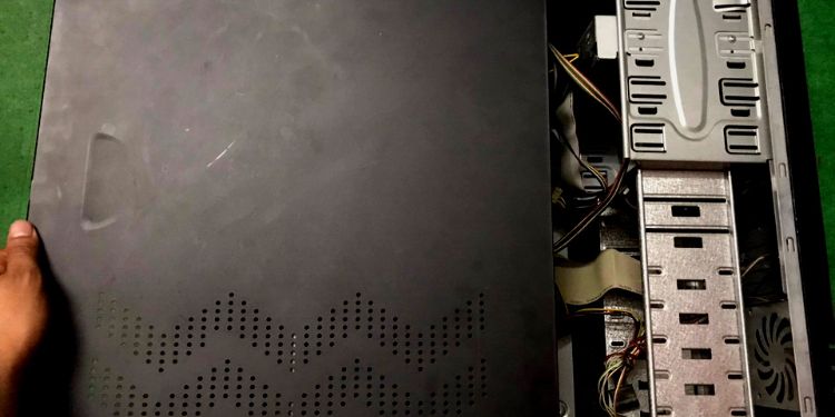
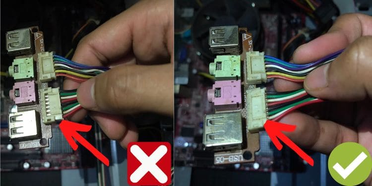
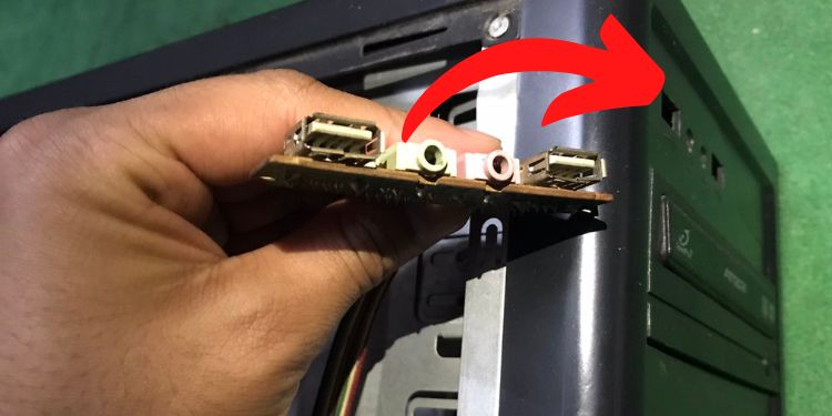
If you’re using a USB 3.0 or above, you’ll likely find a jack instead of individual wires. Thus, it’s relatively easy to connect it to the USB header without having detailed knowledge about the pins and their configuration. Moreover, several USB 2.0 internal cables these days also come with a jack, making the connection quite simple for tech rookies. So, without further delay, let’s jump right into the necessary steps for connecting internal USB header jacks to the USB headers on the motherboard:
Connecting Individual USB Port Wires
If you have an older version of the USB 2.0, you might find a different connector having individual wires for each pin. In such a case, you’ll have to know where each of them needs to be connected. If the wires aren’t properly connected, the PC won’t recognize your USB devices, and in the worst case, this may cause short-circuiting. So, please follow the below procedure to get an idea of how to properly connect the individual USB port wires to the USB headers:
Can I Add More USB Headers?
Generally, most motherboards come with a maximum of two or three USB headers. However, if you’re planning to embed an additional USB header, it’s impossible to do so. Nonetheless, if you have a USB 2.0 adapter supporting a single USB device, you can join two such cables into one. This way, you’ll be able to use two different USB devices using a single USB header: You can even use a USB hub to access a more significant number of USB devices. Basically, the device takes just one USB port from your PC and provides you with several additional USB ports. Lastly, you can also add USB extension cards directly to the PCIe slot in the motherboard. This way, you do not have to worry about additional USB headers.
