Therefore, we have brought you this article so you can easily connect the front panel connectors to the motherboard, even if you are doing it for the first time.
Prerequisites
How to Connect Front Panel Connectors to the Motherboard?
Here is a step-by-step guide on how to connect the front panel connectors to the motherboard.
Ground yourself If you cannot insert the cables, do not force them in. As the pins are very thin and can be bent easily. Do not turn on your computer unless you are absolutely sure that all the cables are placed correctly. Always refer to your motherboard and CPU case user manual if you are unsure about anything.
Find Required Cables From Your CPU Case
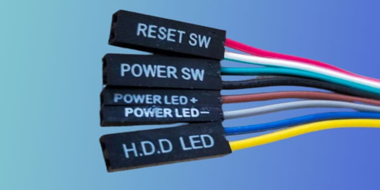
Track the cables that come from the front panel of your CPU case. If you have a heavier CPU case, there will be more cables than this. Here is the list of all front panel cables and how to find them.
Power button cable: says POWER SW at the end of the cable.Reset button cable: says RESET SW at the end of the cable.Power Led lights indicator cable: this will have a + and – sign at the end of the cable.Example: power led is POWER LED+ and POWER LED- or it can be POWER LEDHard disk led indicator: this wire says H.D.D. LED+ and H.D.D. LED- or H.D.D. LED at the end of the cable.
Search Your Motherboard for Front Panel Headers
Search for writings like F_PANEL, JFP1, or FP1 in your motherboard. These writings may be different depending on the motherboard you use. Please refer to the user’s manual if you have issues finding the front panel header. If you don’t have a user manual, use the motherboard manufacturer’s official support page to download the manual. The user manual will have a detailed diagram of the board. Use this to locate the front panel header. Your motherboard will also have a JFP2 or SPK1. This is used to connect a speaker cable from the CPU case.
Find the Positive and Negative Sides of the LED Cable
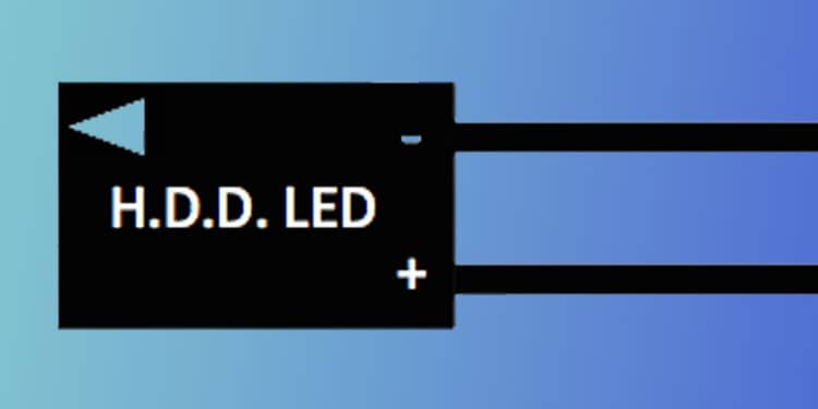
Front panel cables such as the power and the reset button have no polarity (positive and negative signs). So, you can insert them in any way. In case of LED connectors, you should insert the positive end of the front panel cable in the positive pin on the front panel header. POWER SW and RESET SW will have two slots in the cable you need to insert into the front panel headers. On the other hand, the LED may have one or two slots depending on the CPU case manufacturing company. If the LED cables say LED+ or LED-, you can easily insert the wires by following the steps explained below. However, if the cables only say POWER LED or H.D.D. LED, you should figure out the positive and negative slots first. You can see a small triangle on the backside of the LED cables. This indicates the positive end, and the another will be negative.
Connect Your Cables
There will be two sets of pins on your motherboard to connect it to the front panel. One set of pins is called F_PANEL/JFP1/FP1, which holds power, reset, and LED cables. The other one is for the speaker/buzzer, which is called JFP2/SPK1.
Connect F_PANEL/JFP1/FP1
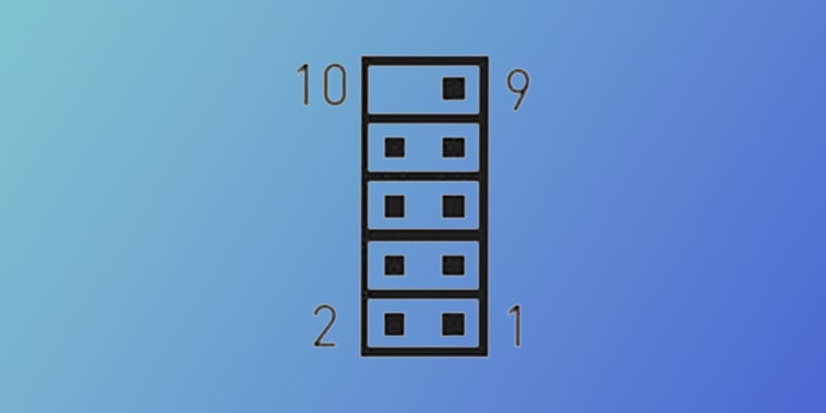
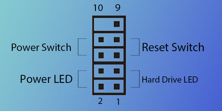
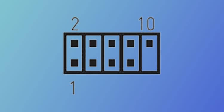
There will be nine pins in your front panel header on your motherboard, as shown below. Make sure that the pin says “JFP1” or “F_PANEL” Your motherboard will also have these numbers written to identify the pins. The pin on one side is odd-numbered, and the pin on the other side is even-numbered. One pin on the top of the even side will be missing. Use the following guide to insert your front panel connectors.
Pin 1 and 3 are for H.D.D LED+ and H.D.D LED- respectively.Pin 2 and 4 are for POWER LED+, and POWER LED- respectively.Pin 5 and 7 for RESET SW.Pin 6 and 8 for POWER SW.Pin 9 will be empty.
The LED light on the front panel will not turn on if you have not matched the positive pins with positive slots and negative pins with negative slots. You can invert and reconnect them if the LED does not turn on.
Connect JFP2/SPK1
This cable comes with the motherboard and not the CPU case. It connects to a small speaker, which beeps error codes. JFP2/SPK1 contains one set of four pins, as shown in the image below. Figure out the positive side of the speaker/buzzer cable. The positive slot goes on the fourth pin.
Related Questions
How to Connect Front Panel USB Connectors?
You can find USB pins on your motherboard. They will have the word USB written under them. Depending on the manufacturer, USB pins may be indicated as JUSB1 or F_USB. If you cannot locate them, please refer to the user manual for your motherboard. One set of USB connectors will have nine pins on them. Now, find the cable from your CPU case that says USB at the end. That cable will have a slot for nine pins. To insert, align the pins and cable and gently insert the connector to the header.
How to Connect the USB 3.0 Front Panel Connector?
Unlike USB 2.0 pins, a USB 3.0 front panel header will have 19 pins on them. This can be located from the JUSB2/F_USB3.0 written near them. To find the cables, check for cables with the color blue at the end, with 20 slots. A small rectangular wall-like structure will surround the pins. On one of the longer sides of the wall, there will be a small gap. To insert the cable, align this gap with the small bulge on the cable.
How to Connect the Front Panel Audio Jack to the Motherboard?
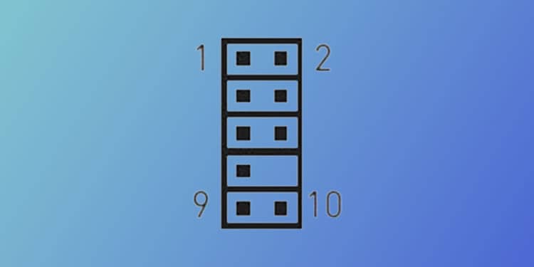
To find the front panel audio connector, search your motherboard for JAUD1/F_AUDIO. This connector will have a slot for ten pins, five on each side, but pin number 8 will be missing. Search for the HD AUDIO cable from your CPU case. The end of this cable will also have holes/slots for ten pins, five on each side. The connector from the case will have one pin slot missing. Align the pins and the cable so that they fit perfectly.